3D Carving Made Easy in Vectric: A Step-by-Step Guide for First-Timers

If you’ve ever stared at a crazy-detailed 3D carving and thought, “There’s no way my CNC can do that,” this is for you. The whole point of the “3D Carving Made Easy” workflow in Vectric is to strip away the mystery and get you from a simple 3D model to an actual carved piece without needing a degree in wizardry or CAM theory.
 

Like most CNC things, there’s no single button. Instead, it's a structured, repeatable process that the software is specifically designed to facilitate. This guide walks through the same process you see in a full Vectric step-by-step tutorial: setting up the job, importing a 3D model, building roughing and finishing toolpaths, previewing, and finally sending it to your CNC router. The focus is on doing your first clean 3D carve, not trying every advanced feature at once.

Before You Start

You don’t need a shop full of industrial gear to get into 3D carving. At minimum, you’ll want VCarve Pro, VCarve Desktop, or Aspire; these are the Vectric programs built for CNC routing and 3D work. On the hardware side, you need a CNC router that can handle the material size you’re working with, plus a couple of cutters. Most beginners start with a straight or spiral end mill for roughing and a small ballnose bit for the final 3D pass. A simple hardwood, MDF, or even a dense foam makes a friendly first material while you dial in your settings.


You don’t need to know everything about feeds and speeds out of the gate, but you do need to know which tool you’re using, what material you’re cutting, and have at least a “reasonable” starting point for RPM and feedrate. Fine-tuning comes later.

Alt image

Step 1: Set Up the Job in Vectric

Open your Vectric software and create a new job. This is where you tell the software what world it’s working in: how big your stock is, how thick it is, and where “zero” lives.
 

Set the X and Y sizes to match your actual material. If you’re carving a plaque that’s 10 inches wide by 8 inches tall, those are your job dimensions. Set the Z thickness to your measured material thickness, not the number printed on a sticker from the lumber rack. A set of calipers is your friend here.
 

Next, choose your Z zero position. For most simple 3D projects, zeroing on the top of the material is the easiest mental model: the top of the board in the software matches the top of the board on the machine. You can also choose to zero off the machine bed, but that’s easier to use once you’re more comfortable with workholding and consistent material thickness.
 

Finally, choose your XY datum point. Many folks like the lower-left corner because it’s easy to find and matches most tutorials, but center-zero can be very handy for round or irregular blanks. As long as what you tell Vectric matches what you do on the actual CNC, either will work.
 

Once the job is created, you’ll see your “board” in the 2D and 3D views, and you’re ready to bring in your 3D model.
 

Step 2: Import and Position the 3D Model

On the modeling side of the interface, use the option to import a 3D component or model. Vectric supports common formats like STL and its own clipart components. Many users start by practicing with the built-in 3D clipart because you know those models are clean, scaled reasonably, and designed for carving. 
 

Once imported, the model appears as a “component” that you can scale, move, rotate, and raise or lower within the material. This part matters more than beginners realize. If you scale the model to be too tall for your material thickness, you’ll either carve through the back or lose detail because the model gets “squashed” when you limit it.
 

Use the model height control to fit the design comfortably inside the thickness of the board. A common approach is to leave a little “safety” thickness under the deepest point of the carve so you don’t accidentally punch through, especially on planed lumber that might not be perfectly uniform.
 

Position the model where you want it in XY. For a sign or plaque, that usually means centering it. For a panel with multiple elements, you can combine several components in one layout, but for a first project, a single 3D model in the middle of the board is plenty.
 

Make sure the model is set to “add” or “merge” in a way that makes sense for your design. Aspire users playing with multiple components can use different combine modes, but the core idea is simple: the 3D surface you see in the preview is exactly what the toolpaths are going to follow.

Step 3: Choose Your Tools and Define Them in the Tool Database

Before you can generate any 3D toolpaths, Vectric needs to know what cutters you plan to use. For a basic 3D carve, you almost always run two passes: a roughing pass and a finishing pass. 
 

The roughing pass uses a sturdier tool, usually an end mill, to hog out most of the material quickly. This pass doesn’t worry much about surface quality; its job is to get close to the final shape without snapping tools or bogging down the router.
 

The finishing pass uses a ballnose bit, often something like a 1/8" or 1/4" ballnose, depending on the scale of the design. The smaller the stepover, the finer the final surface, but the longer the carve takes. That tradeoff between speed and detail is at the heart of 3D carving.
 

In Vectric’s tool database, define each tool with diameter, flute length, pass depth, stepover, and your starting feeds and speeds. You can use conservative defaults from your CNC manufacturer or reputable feeds-and-speeds references, then adjust based on how your machine behaves.


See also: IDC Woodcraft's downloadable databases for Vectric and other common software. 
 

The important thing is consistency: if you tell Vectric you’re using a 1/4" ballnose and then physically load a 1/8" bit, everything else will be wrong. Keep your virtual tools matched to the real ones in your Collet.

Step 4: Create the 3D Roughing Toolpath

With the model in place and tools defined, generate a 3D roughing toolpath. In the toolpath tab, choose the roughing strategy. This tells the software to remove bulk material in layered passes following the model's contour, while leaving a small “allowance” of material so the finishing tool has something to clean up.
 

Select your roughing tool, usually that end mill. Set the machining allowance to a small value; something like half a millimeter to a millimeter (or around twenty to forty thousandths of an inch) is typical. Too much allowance and the finishing pass has to cut too heavily; too little and you risk the roughing step leaving gouges in steep areas.
 

Choose how you want the tool to raster across the material. A simple zig-zag pattern is fine for most shapes. Pay attention to your pass depth; you want each layer to be within the limits of your machine and material without chatter.
 

Once you’ve set the parameters, calculate the toolpath. You’ll see the roughing passes drawn over the model and can preview the roughing cut. In the 3D preview, it will look “chunky” and stepped—that’s normal. The finishing pass is where the magic happens.

Step 5: Create the 3D Finishing Toolpath

Now create the 3D finishing toolpath and select your ballnose bit. This is where you care deeply about stepover. A large stepover cuts faster but leaves visible scallops and ridges; a smaller stepover smooths everything out at the cost of time. Many carvers settle into a middle ground that looks good off the machine but doesn’t run for twelve hours. 
 

Choose a strategy such as raster or offset. Raster runs back and forth in straight lines, which is easy to visualize. Offset spirals around shapes, often producing a nicer finish on curved models, but sometimes adding complexity where there are sharp corners. You can also experiment with running a second finishing pass at 90 degrees to the first for extra detail, but that’s icing on the cake, not a requirement for a first-time project.
 

Make sure you’re machining the entire model boundary and that your boundary offset gives the bit enough room to “roll over” the edges cleanly instead of stopping dead at the model edge and leaving a little vertical wall. Then calculate the toolpath and watch it in the preview window.
 

Run the 3D preview for both roughing and finishing. Spin the virtual model around and inspect it. If you see any gouges, clipped areas, or weird flat spots, this is the time to fix them, not when there’s already sawdust on the floor.

Step 6: Preview, Sanity-Check, and Adjust

The 3D preview in Vectric is not just eye candy; it’s basically a simulation of what your toolpaths will do to real material. Use it aggressively. Check that the model is not taller than your stock. If the deepest part of the carve looks like it’s right at the bottom surface, consider lowering the model height slightly or starting with thicker stock. Make sure your Z-zero choice in the job setup matches the way you actually plan to set zero on the machine.
 

Look at the tooling marks in the preview. Even though it’s a simulation, you can get a sense of whether your stepover is too coarse. If you can clearly see big “ridges” across the whole model, consider dropping the stepover a bit. That will add time, but it will save you hours of sanding in many cases. 
 

If everything looks good, save your toolpaths. Many users save the roughing and finishing passes as separate files using the correct post processor for their CNC controller. Label them clearly so you don’t accidentally run the finishing file first.

Step 7: Run the Carve on Your CNC

Now the software part is done; it’s time to make chips. Secure your material to the spoilboard using clamps, screws, or a vacuum table - whatever system you trust. For 3D carving, solid workholding matters a lot, because the bit is constantly moving in X, Y, and Z and any small shift in the stock shows up as ugly artifacts in the final surface.
 

Home your machine if needed, then jog to your chosen XY datum and set zero there. Set your Z zero on the top of the material if that’s what you chose in Vectric. Double-check that your tool in the spindle matches the tool selected in the toolpath.
 

Before going full send, many people like to run an air cut: run the roughing job with the Z raised so the bit doesn’t actually touch the material. That way, you can watch the motion and make sure nothing weird is happening with scaling, direction, or travel limits.
 

Once you’re confident, lower Z to the real zero, hit start, and let the roughing pass run. After roughing, swap in the ballnose bit, reset Z zero if your machine doesn’t have an automatic tool length sensor, and run the finishing pass. This is the satisfying part: you gradually watch the “stepped” roughing surface transform into smooth curves and detailed shapes.

Step 8: Cleaning Up and Finishing the Carve

There are some best practices to get the cleanest possible cuts, including using down bits when necessary, but you'll likely always need to brush or sand.

After the machine stops, you’ll usually have some fuzzies, tool marks, or little ridges, especially in woods with open grain. A quick pass with a stiff brush and some light sanding with flexible sanding pads or small strips of sandpaper can bring out the detail without rounding everything over.
 

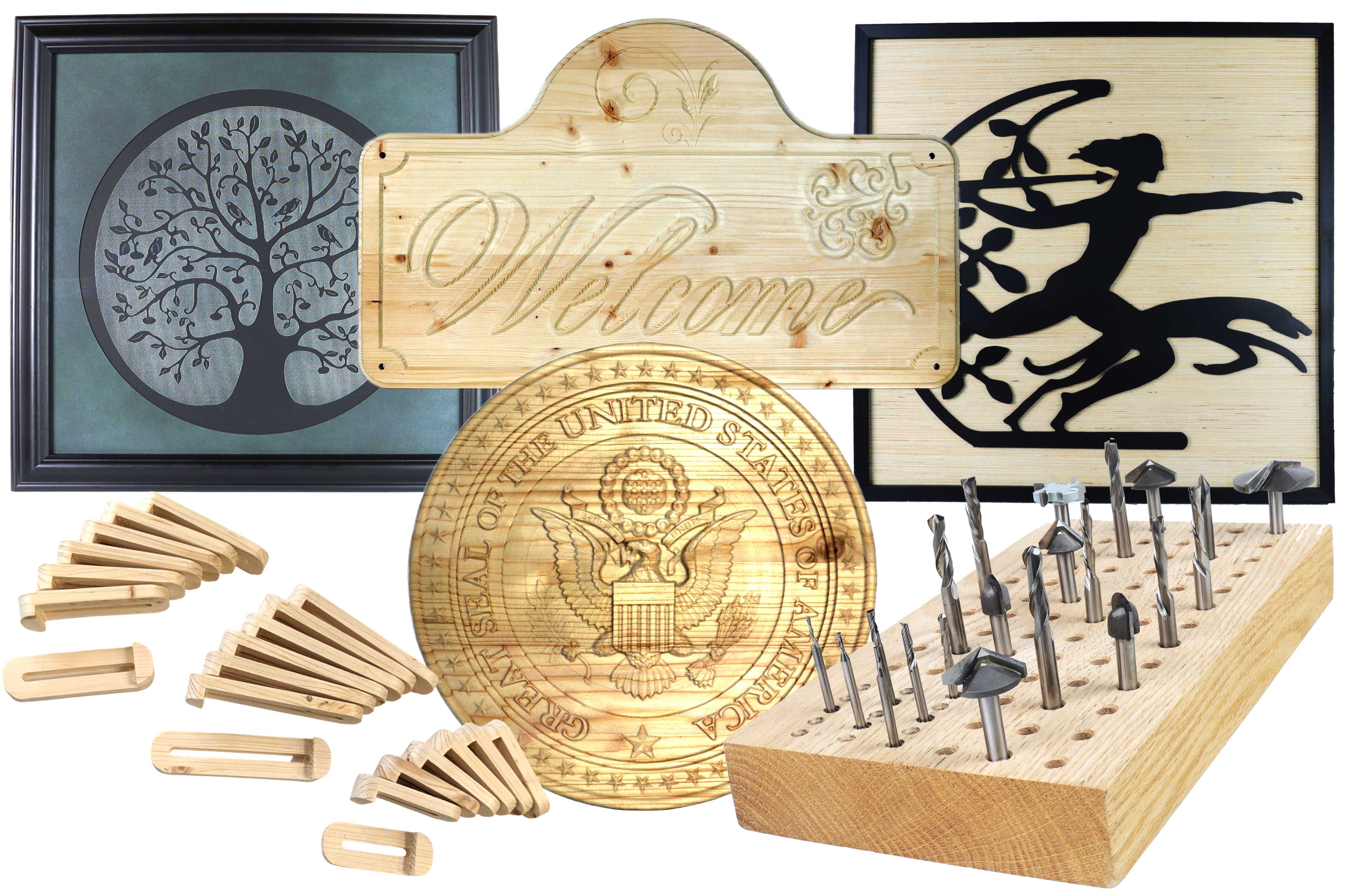
From here, you can stain, paint, clear-coat, glaze, or even paint-and-wipe to pop the shadows in deeper areas. The nice thing about a well-cut 3D surface is that almost any finish looks good because the geometry itself is doing the visual heavy lifting.
 

Once you’ve successfully run one full start-to-finish 3D carve in Vectric, you’ve essentially unlocked the core workflow: define the job, import or model the design, create a roughing and finishing toolpath, preview, and cut. That pattern repeats, whether you’re carving a simple plaque, a detailed relief, or eventually doing more complex projects like multi-sided carves and rotary work. 
 

From here, you can start experimenting with more advanced features: combining multiple 3D components, adding 2D V-carved text on top of a 3D background, splitting a large relief into tiles, or creating your own models in Aspire.