Free Shipping for CNC Bit orders over $160

Shop

Shop By Project

Shop By Type

Starter Sets

Starter Sets

Inlay

Inlay

3D Carving

3D Carving

Acrylic

Acrylic

Engraving

Engraving

Bowl And Tray

Bowl And Tray

Digital Files

Digital Files

Slotting

Slotting

Rounding

Rounding

V Grooving

V Grooving

Surfacing

Surfacing

Starter Sets

Starter Sets

Bit Bundles

Bit Bundles

Ball Nose

Ball Nose

Compression

Compression

Downcut

Downcut

Drills

Drills

Engraving

Engraving

Extended Cut

Extended Cut

Roughing

Roughing

Rounding

Rounding

Slotting

Slotting

Straight Cut

Straight Cut

Surfacing

Surfacing

Upcut

Upcut

V Grooving

V Grooving

Jenny Bits

Jenny Bits

Collets

Collets

Accessories

Accessories

CNC Machines

CNC Machines

Vacuum Tables

Vacuum Tables

Spindles

Spindles

Software

Software

Digital Files

Digital Files

Merch

Merch

Closeout

Closeout

CNC Resources

Database Downloads

About

Contact Us

Get A Gift Card

Shop

Shop By Project

Shop By Type

Starter Sets

Starter Sets

Inlay

Inlay

3D Carving

3D Carving

Acrylic

Acrylic

Engraving

Engraving

Bowl And Tray

Bowl And Tray

Digital Files

Digital Files

Slotting

Slotting

Rounding

Rounding

V Grooving

V Grooving

Surfacing

Surfacing

Starter Sets

Starter Sets

Bit Bundles

Bit Bundles

Ball Nose

Ball Nose

Compression

Compression

Downcut

Downcut

Drills

Drills

Engraving

Engraving

Extended Cut

Extended Cut

Roughing

Roughing

Rounding

Rounding

Slotting

Slotting

Straight Cut

Straight Cut

Surfacing

Surfacing

Upcut

Upcut

V Grooving

V Grooving

Jenny Bits

Jenny Bits

Collets

Collets

Accessories

Accessories

CNC Machines

CNC Machines

Vacuum Tables

Vacuum Tables

Spindles

Spindles

Software

Software

Digital Files

Digital Files

Merch

Merch

Closeout

Closeout

CNC Resources

Database Downloads

About

Contact Us

Get A Gift Card

The 10 Step Method for Surfacing a CNC Router Spoilboard

The Short Answer: CNC spoilboard surfacing is the process of lightly machining the sacrificial board beneath your workpiece so it is flat relative to your CNC router’s actual cutting motion. A surfaced spoilboard gives you more consistent cutting depth, cleaner pockets, better engraving results, and a more reliable base for every woodworking project that follows.


A new CNC spoilboard may look flat, but it is rarely perfectly parallel with the motion of your gantry and spindle. Even a small difference in height can leave one side of a project shallow and another side too deep. 


The process below walks through how to tram the machine, measure usable travel, build a safe surfacing toolpath, set feeds and speeds, and make shallow passes until the spoilboard surface is fully cleaned up.

Alt image

What is a CNC Spoilboard?


A spoilboard, sometimes called a sacrificial board, is the board your material sits on during CNC work. It protects the machine bed when a profile cut goes through the workpiece, and it provides a consistent surface for clamping. 


Most CNC routers use MDF because it is flat, uniform, and easy to machine. Particle board can work in some situations, but MDF is generally the more consistent choice for spoilboard resurfacing. 


The goal is not to make the board flat relative to the floor. It is to make the spoilboard surface flat relative to the CNC machine’s X, Y, and Z movement so the router bit produces more consistent cutting depths across the work area.


Before You Start: Tram the Machine

Tramming means the spindle or router is perpendicular to the spoilboard. If it leans slightly left, right, forward, or back, the surfacing router bit will cut on an angle. The result is often faint ridges, visible lines, or small steps across a large area.

Check tram before surfacing, then check it again after the first full cleanup pass. For surfacing, use a purpose built surfacing router bit rather than a small straight bit or compression bit. 


Do a quick tram check before surfacing. After you surface the board, check tramming again and fine-tune if needed. This order gives you a better chance of ending with a spoilboard that feels flat and produces clean cuts.


For the most accurate and rigid alignment, we recommend using a dedicated measuring tool rather than improvising. You can pick up our professional grade router tram bar to dial in your spindle alignment with high precision. When you’re ready to surface, always use a purpose-built surfacing router bit rather than a standard bit to ensure an ultra smooth finish


Important: Do not try to surface your way out of a machine that is out of tram.
 

Alt image

Homing Switches and Working Area

Surfacing is a controlled face-milling operation across a large surface area. Before creating the toolpath, you need the true usable travel of your CNC router.


If your CNC machine has homing switches, run the homing sequence first. The controller should recognize its home position and enforce soft limits, which helps prevent the machine from traveling beyond its configured range.

If your machine does not have homing switches, you can still surface the spoilboard safely. You just need to avoid pushing the machine into its hard stops. When a machine contacts a hard stop but the controller continues counting movement, the displayed position no longer matches the machine’s real position.


Pro Tip: Take your time during this step. The surfacing toolpath should cover as much of the spoilboard as the router can safely reach, but it should never run into the machine’s physical limits.

The 10 Step CNC Spoilboard Surfacing Method

Step 1: Find Your True X and Y Travel

Start by finding the maximum safe travel in the X and Y directions. 

With Homing Switches

On a machine with homing switches, home the CNC router. Set X and Y zero at the home position, then jog diagonally toward the far corner until the software reaches its soft limits. Record the maximum X and Y values shown in the controller.

Without Homing Switches

On a machine without homing switches, move the machine carefully to the chosen reference corner, often the front-left. Bring it close to the hard stops, then back away slightly at a slow jog speed. Set X and Y zero once the machine is no longer pressing against a stop.


Then jog toward the far side and far end, stopping just short of the physical limits. Record the values in the controller and round down slightly if needed. “Close but not touching” is safer than using every last fraction of travel.

Step 2: Create the Job in CAD/CAM Software

Open your CAD/CAM software and create a job that matches the working-area dimensions you measured. If your usable area is 49 by 49 inches, create a job at those dimensions rather than using the full, advertised machine size.


Set the job origin to match the corner you used when zeroing X and Y. For example, use a front-left origin if you zeroed at the front-left corner of the machine. The software coordinates must match the real-world reference point on the spoilboard.


Create a rectangle the exact size of your working area and place it at X0, Y0. This rectangle becomes the boundary for the surfacing toolpath.

Step 3: Choose the Right Surfacing Bit


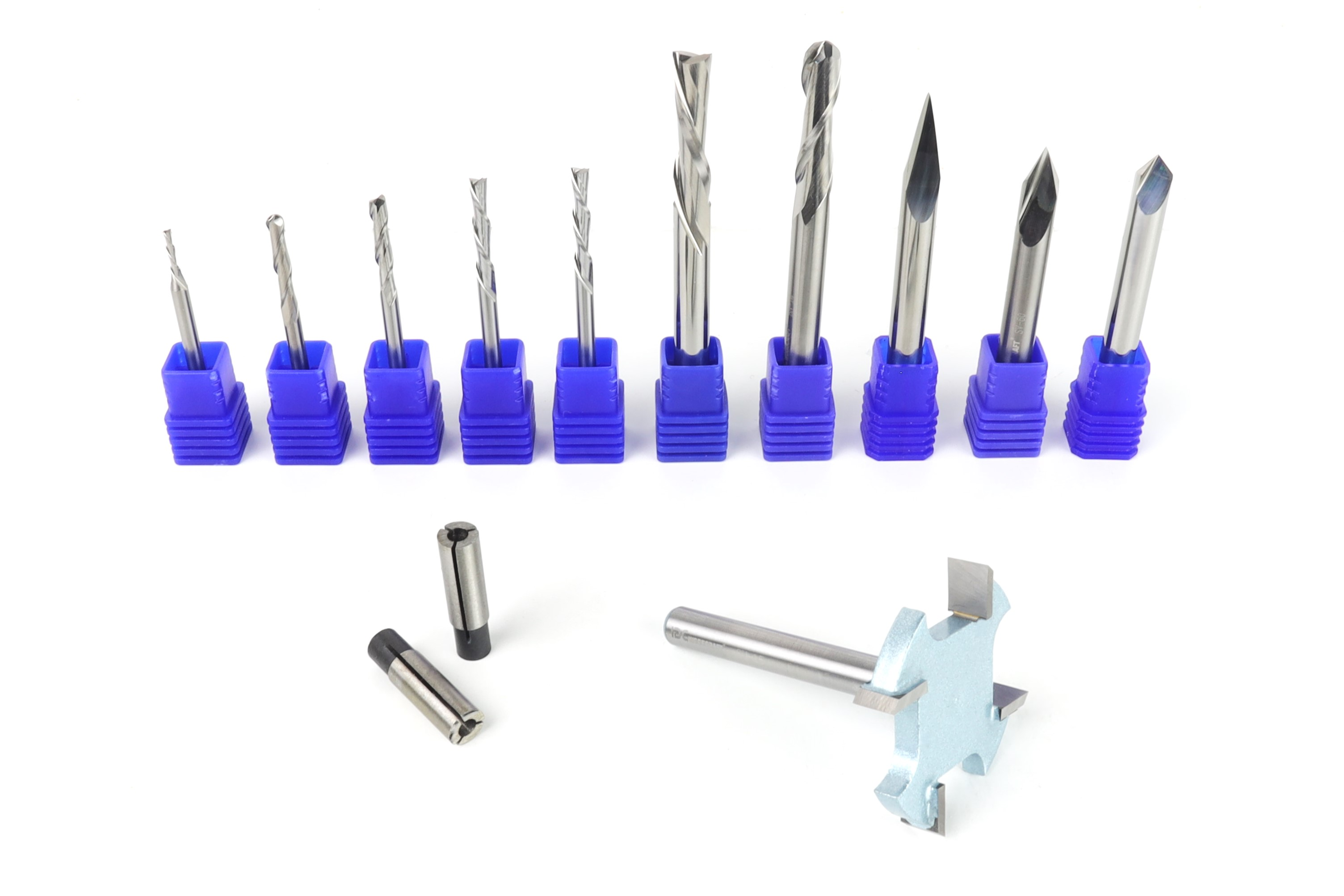
A surfacing bit is designed to machine a wide, flat area. Its larger diameter reduces cycle time compared with a small router bit because it covers more surface with each pass.


Choose a bit that matches your collet. Many hobby CNC routers use a 1/4-inch shank, while compact desktop machines may use a 1/8-inch shank. 


Pro Tip: Do not use a handheld-router bit with a guide bearing, such as a flush trim bit, on a CNC router. The CNC controls the path, so a bearing-guided tool can interfere with the workpiece or spoilboard.


Step 4: Set a Ramped Entry Instead of Plunging

A wide surfacing bit is not a plunge-cutting tool. Plunging straight down can force the center of the bit into the MDF while the outer cutting edges are still trying to engage, creating heat, chatter, or burn marks.


Use a ramp entry instead. A zigzag ramp is a practical choice in many CAM programs because it lets the surfacing router bit ease into the material.


As a starting point, set the ramp length to about three to four times the cutter diameter. For a 1.5-inch surfacing bit, that works out to roughly 4.5 to 6 inches of ramp distance. The goal is a gradual entry, not a sudden plunge cut.

Step 5: Build a Perimeter Profile and Raster Pocket Toolpath

Create two toolpaths for a predictable CNC spoilboard surfacing job. 


First, create a shallow profile toolpath on the line of the rectangle. This pass defines the outer edge of the area you are surfacing. Set a shallow depth, such as 0.01 inch.


Second, create a pocket toolpath that clears the entire area inside the rectangle. Choose a raster pattern rather than a spiral or offset pattern. A raster toolpath moves back and forth in straight rows, maintaining more consistent motion across the board.


Pro Tip: Use the same shallow cut depth for both toolpaths, and enable ramping for the pocket toolpath as well.

Step 6: Set Conservative Feeds and Speeds

Surfacing uses a wide cutter with multiple cutting edges contacting a large area. Start with sensible feeds and speeds, then adjust based on your machine’s rigidity, spindle or router power, and cut quality.


Watch for burn marks, chatter, unusual noise, or packed dust. Those signs tell you the feed rate, RPM, depth of cut, or dust collection setup needs adjustment. IDC Woodcraft’s Chipload Calculator can help you check feed rate, RPM, flute count, and tool diameter before starting a new job. For an even quicker setup, you can also download IDC Woodcraft’s pre-built feeds and speeds tools database to import your parameters directly into your CAM software.  

Step 7: Run a Dry Test First

Before installing the surfacing bit, run the toolpath with the Z axis raised well above the spoilboard. This is the easiest way to catch an incorrect origin, oversized job boundary, or toolpath that tries to move outside the usable area.


Watch the machine as it moves around the perimeter and across the board. Confirm that the motion stays safely inside the work area and that the X and Y zero point matches the origin in your software.


A dry run takes only a few minutes and can prevent an avoidable crash.

Step 8: Install the Bit and Set Z Zero

Install the surfacing bit with enough of the shank seated in the collet for a secure grip. For a typical shank bit, about two-thirds of the shank inside the collet is a general target. Do not grip the fluted cutting area, and do not extend the tool farther than necessary.


Pro Tip: Overextending a bit can increase vibration, chatter, and also puts more stress on the router, spindle, and tool.


Set Z zero with a touch probe or the paper method. For the paper method, place paper on the spoilboard, jog the tool down slowly until the bit catches the paper with light friction, then set Z zero. Remove the paper before running the job.

Step 9: Turn on Dust Collection and Surface in Shallow Passes

MDF produces fine dust quickly during surfacing. Use a vacuum table and wear a properly fitted dust mask when needed. Fine dust can settle into machine components and makes it harder to see the cut.


Mark the spoilboard with pencil lines before the first pass. After the toolpath finishes, the remaining lines show which areas the surfacing bit did not reach.


If pencil marks remain, lower Z by another 0.01 inch and run the same toolpath again. Repeat until the pencil marks disappear and the full spoilboard surface has been cleaned up.

Several shallow passes are safer than removing too much material at once. The goal is to remove the minimum amount of material needed for a full cleanup and smooth finish.

Step 10: Check for Ridges and Lightly Sand

After surfacing, you may see faint visual lines from the raster stepover. That is normal. What matters is whether you can feel ridges when you run your hand across the spoilboard.

If you feel any noticeable steps, check the router or spindle tram again. A surface that looks striped but feels flat is usually fine. A surface with physical ridges points to a tramming issue rather than a spoilboard problem.

Finish with a light hand sanding, but do not sand aggressively. You are only smoothing light fuzz, not changing the flatness you just created.

Common CNC Spoilboard Surfacing Problems

Even a careful setup can run into a few problems during spoilboard surfacing. Use this chart to identify common issues, understand what may be causing them, and make the right adjustment before your next pass.

Problem Likely Cause What to Do
Burn marks RPM too high, feed too slow, or toolpath pauses Use a raster path, lower RPM, or increase feed carefully
Ridges you can feel Router or spindle out of tram Adjust tram, then make another shallow pass
Untouched areas Spoilboard is uneven Lower Z by 0.01 inch and repeat
Rough or fuzzy surface Dull bit or overly aggressive cut Inspect the bit and reduce cut depth
Dust packed in the cut Weak dust collection or insufficient chip clearing Improve airflow and confirm feed settings
Toolpath runs too far Job size or origin does not match machine travel Recheck X/Y travel and run another dry test

Surface Your Spoilboard with IDC Woodcraft

A flat spoilboard gives every project a better starting point, and IDC Woodcraft has free beginner CNC resources to help you build confidence with machine setup, tooling, and everyday CNC techniques.


When you are ready to resurface your spoilboard, browse the IDC Woodcraft Surfacing Bit Collection to find a cutter sized for your CNC router and collet. Get started today and give your next project a flatter, more consistent foundation.